HomeServ is a project that makes you able to control your electrical devices such as a light from HomeKit in your iOS device. This means you can control everything with Siri, or with the panel in the control center or in the Home app, without loading times, without any third-party application.
Here is a video about HomeServ :
So, let’s build it !
1. Things you need
- A Raspberry Pi (I personally use the Model 3 in order to have WiFi)
- A SD card to store data and Operating System from the Pi (8gb or above)
- A power adapter (5V 2A min) and a USB into Micro-USB cable in order to power the Pi
- A box to protect the system
Other differents parts will be needed depending on the devices you want to control.
- If you want to control an I/O device that can be normally turned on and off by an outlet, you will need relay module, that will act as a switch (take as much relays as devices you need to control)
- If you want to build your own RBG light, WS2812B or SK6812-based LEDs. I advice the NeoPixel rings from Adafruit.
- If you want to make a lock mecanism, a solenoid, its power adapter and a relay module.
2. Software
If you start from zero with the Raspberry Pi, follow this steps in order to get your Raspberry Pi ready to work :
Download Raspbian, the operating system for your Pi.
Download Etcher and install it.
Connect the micro-SD card through the adapter.
Launch Etcher and select the .img or .zip Raspbian file you’ve downloaded.
Select the SD card and click Flash, then wait for it to be ok.
Unplug your SD card and plug it in your Raspberry Pi.
Connect your Pi to a screen with HDMI, to power with Micro-USB, to network with Ethernet and to a keyboard with USB.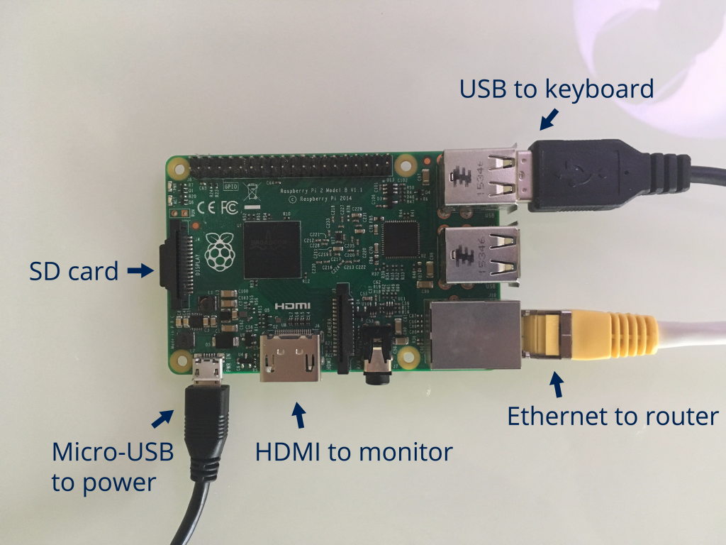
The Raspberry Pi will boot. Then, it will ask you for your login : type « pi » and for your password : « raspberry ». The keyboard is set to qwerty, so you may have to type « raspberry » differently.
Type
sudo raspi-config
First, go to change user password and follow the instruction to change the default « raspberry » password for a better security.
Then, go to « Interfacing options » and select « SSH » and enable it.
Finally, reboot your pi when asked.
Now, let’s setup the WiFi on your Pi if you have WiFi on it : type in
sudo nano /etc/wpa_supplicant/wpa_supplicant.conf
Add the lines
network={
    ssid="wifiname"
    psk="password"
}
Then type ctrl+x, then y, then enter.
Where wifiname is replaced by the name of your WiFi network and password by its password.
To get the local IP adress of your PI, type
ifconfig
If you have set up the Wifi, note the inet addr in wlan0, for example for me : 192.168.1.76.
If you didn’t and you are connected to Internet over Ethernet, note the inet addr in eth0.
Now you can access your Pi over SSH, that means you can put it in its bow without any other cable than the power one, and you can control it from your computer.
To do this, install PuTTY if you’re using Windows, and in « SSH » tab, type in the IP adress got before. Type « connect » and enter « pi » for the login then your password.
If you’re using a Linux distribution or macOS, open the terminal, then type in
ssh pi@ipadress
You can now follow the rest of the guide.
Access your Pi over SSH with your default computer.
Now that you’re connected to your Pi over SSH, let’s install all the needed software for HomeServ !
HomeServ is based on HAP-NodeJS by KhaosT, a software that acts as a HomeKit bridge. HomeServ adds actions when the simulated devices are triggered.
To install it, run the following commands :
Download a script to easily install all the stuff:
wget http://antoinepegne.fr/wp-content/uploads/2017/07/homeserv_install.zip
Unzip the downloaded file.
unzip homeserv_install.zip
Get the rights.
sudo chmod a+x homeserv_install/script1.sh && sudo chmod a+x homeserv_install/script2.sh
Run it.
sudo bash -x homeserv_install/script1.sh
The Pi will run several commands, sometimes asking you for your permission. Type « y » then Enter.
Then, the Pi will automatically reboot. At the end of that reboot, log in over SSH and type this command
sudo bash -x homeserv_install/script2.sh
HomeServ should now be installed on your Pi. Try to type the following command to launch it :
homeserv
Now open up the Home app on your iOS 10+ device. If you use an older version, download an app such as elgato eve.
Create a new home, then tap « Add accessories ».
Select the HomeServ accessory, then tap » Add anyway », then « Enter code Manually », and then type the code « 031-45-154 ».
The setup you have then will depend on you type of device. For the lock, select the location and name it by taping its name. For the outlet, select the type of device (light, fan or simple outlet), and name it. If you chose a lamp, you can customize the icon by taping it. Finally, choose your settings for the RGB lights.
You can now access your devices in the Home app, in the Control center or with Siri !
3. Electronics
Now that the software part is completed, let’s jump to the hardware part. It will be divided in three sections, one for each of the devices you can control with HomeServ.
Outlet
HomeServ enables you to control a simple outlet for I/O devices such as a fan, a light or other devices.
Be really safe, since you will need to work on high voltage, so follow the instructions i give you !
In order to do this, i cut the power wire of the device (⚠️ Verify the device is not plugged in before doing this ⚠️). Then I used a relay module in order to control the power in the device. A relay is a component that basically acts as a switch, except that it is controlled by the Raspberry Pi.
The relay module has two sides for the connection. The side with terminal block is the one we will use in order to plug in the device. The relay must act as a switch. When it’s powered, there is a connection between COM (common) and NO (normally open). When it’s not powered, there is a connection between COM and NC (normally close). In the power cable you should have two wires. Solder the two ends of one and isolate the solder. Be careful that the wires you solder together were the same wire before you cut it, and that you didn’t invert them. For the other cable, plus one end in COM and the other in NO, and screw in the terminal blocks. On the other side, you should have some pins, depending on how much relays you have on the module. With jumper wires, plug in VIN to the 5V GPIO on the Pi, GND to the GND on the Pi and INX, where X is the number of your relay, to GPIO21 on the Pi. The GPIO are the header pins on the side of the Pi. You can know which is one with this picture from raspberrypi-spy.co.uk : 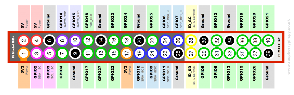
The number X of the GPIO is writed GPIOX, it’s not the numer in the circle !
⚠️ Don’t forget to protect you relays in a box/case in order to protect people from shocks ! ⚠️
Now that the relays are installed and protected, you can plug in your Pi and try to change the status of the accessory. If the relays do a little click, that means everything is working properly, and you can plus in your accessory. If you want a picture for the connections, go to the lock section and replace the solenoid by the outlet.
I prevented you about the risks of this manipulation, i’m not responsible of any problem you may have !
Light
The color light is much less risky to build. You can build a normal light, like I did with add of neopixel rings. You will have three wires to connect : the 5V/VIN, the GND and the DIN.
Connect the 5V and GND to an external 5V supply, since NeoPixels draw a lot of current the Pi cannot handle. Connect the DIN wire to GPIO18 on the Pi and the GND to GND on the Pi. The wiring should look like this :![]()
Put these Pixels anywhere you want and control them with a hard press on the light button if you have a 3D Touch-ready iPhone, or a long press in the other case. What I did is put them instead of the actual bulb in a lamp, and removed the default wires. (⚠️ Only do this when the light is unplugged ⚠️)
Lock
The lock system is pretty much the same as the outlet one, except that instead of using the relays as a switch for the outlet, we use them between the lock solenoid and its power plug. The INR pin, where R is the number of the relay you use for the relay, is connected to the GPIO20 on the Pi and the 5V and GND to the same GPIOs on the PI.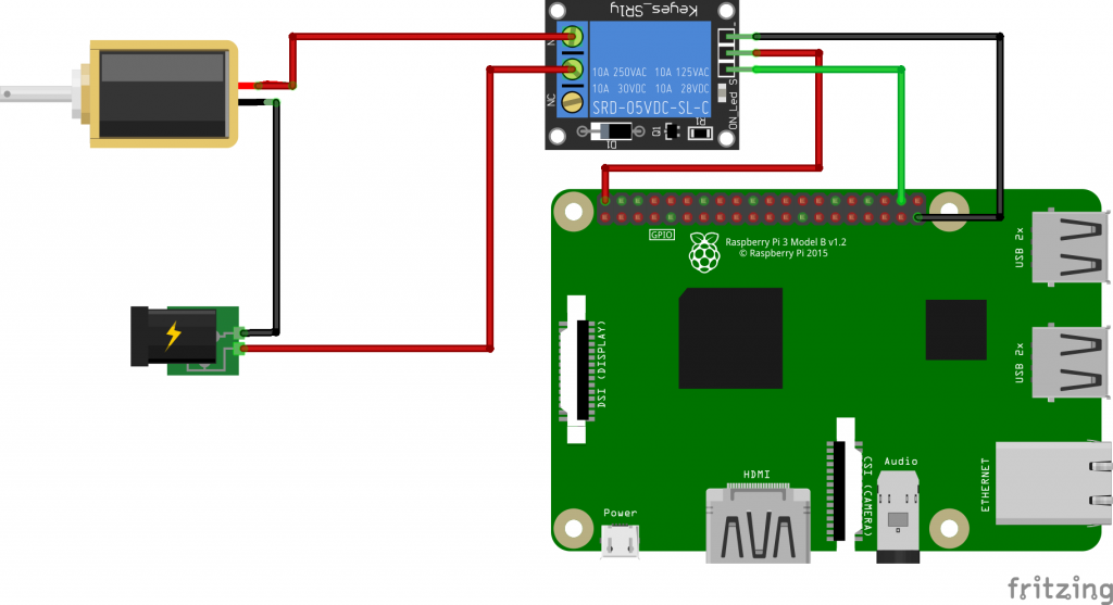 You can use the same relay module for the outlet and lock if you have multiple relays on the module. In this case, you only will need to plug in 5V to 5V on the Pi, GND to GND on the Pi, IN1 to GPIO21 and IN2 to GPIO20 if the outlet is connected to the relay 1 and the lock to relay 2.